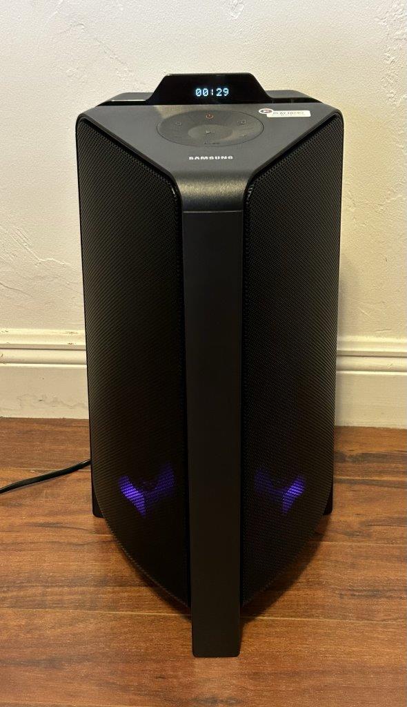
Samsung Bluetooth Speaker USB Audio

Recently purchased a Samsung MX-T40 Bluetooth speaker. Its a nice box, sounds good, but at the same time has me ask serious questions about activities in software engineering. This device has many capabilities including Bluetooth streaming and USB audio playback. I learn that the USB audio playback has a rather serious omission that really should have kept this thing from getting through system test.

Samsung MX-T40

The device has support for two concurrently connected Bluetooth devices (one can play at a time), has a remote control that actually works and has support for playing audio content from a USB source (USB thumb drive). USB audio is the focus on this post.

So I fed it a USB stick with several hundred audio files on it – taken from car, ready to go…

Play sound, sounds good! And the remote works, play things. .

Getting to the issue

Then hit “off”. Come back later and “on”. Select USB and hit play – it starts over at the beginning of the list of songs, sorted alphabetically, so it starts at U2 “40” each time the machine is started up. Side question is why did I have to select USB when it was playing USB when I turned the speaker off?

Keep in mind, it never lost power – it was “off”, but here is no such thing as “off” as the device never lost power. Compare to a car – where the USB playback picks up when you start the car immediately, where it was when you turned the car off.

Amazed that this could happen in a production music appliance, I sought out firmware update for the fix. Surely this is fixed. Found the Samsung download page and downloaded both available firmware updates, and installed.

Survey says: No change in behavior. Disappointing. Instead of “off”, I’ll just leave the machine always on and hit pause. This is probably not great for energy star scores…

Firmware downloads

HMC-TX0WWB-1038.zip for Main IC dated October 13, 2021
HMC-T40WWT-xxxx.zip for Bluetooth IC dated December 14, 2020

Today being February 2023, this means that the device has received all the firmware updates that it likely will receive – and it will never learn to remember it’s position in USB audio playback.

Guess I should get with the youngsters and stream everything all the time.

Joe Nord

WifiRanger Aspen – Dinali connection

In pre-trip testing, discovered that the WifiRanger Apsen -> Dinali -> house WiFi was struggling to maintain a connection. Near constant power cycles were required to get a computer to connect. Debugged and concluded that the Dinali and likely also the newer Everest must be connected to the Aspen on LAN port #1, and learned more importantly, that LAN port #1 on the Aspen is the port labeled “4”.

Background

The WifiRanger “Aspen” is a small WiFi router that is “inside the boat” and connects to an “outside the boat” weather resistant “Dinali” or “Everest” for connection to the external WiFi source. From here on, I will discuss the Aspen and the Dinali as this is my configuration.

The brains of the operation is the little Aspen box and the remote piece is the Dinali. Both run the same software and both can individually do the job of acting as a WiFi router. The advantage of the dual configuration is that the Aspen (inside the boat) provides WiFi to the things inside the boat, and the Dinali (on top of the boat and unobstructed) takes care of the WiFi connection to the house, marina, RV park. Note that the Dinali being outside, is inside of a weather protected case and the Aspen being inside looks like a normal home WiFi router.

Back to todays debug

Observed behavior is that WiFi on the boat was “not reliable”. Can connect, but connection won’t stay up. It had been a couple months since last used and when logged into the Aspen’s web console, it said that a firmware update was available, would you like to install. Sure. Upgrade of firmware was conducted from 7.1.0b9 to 7.1.0b11 and nicely the tethered connection of the Aspen and Denali had both of them upgraded in a single go. No issues on the firmware upgrade, but it changed nothing for the connection staying alive.

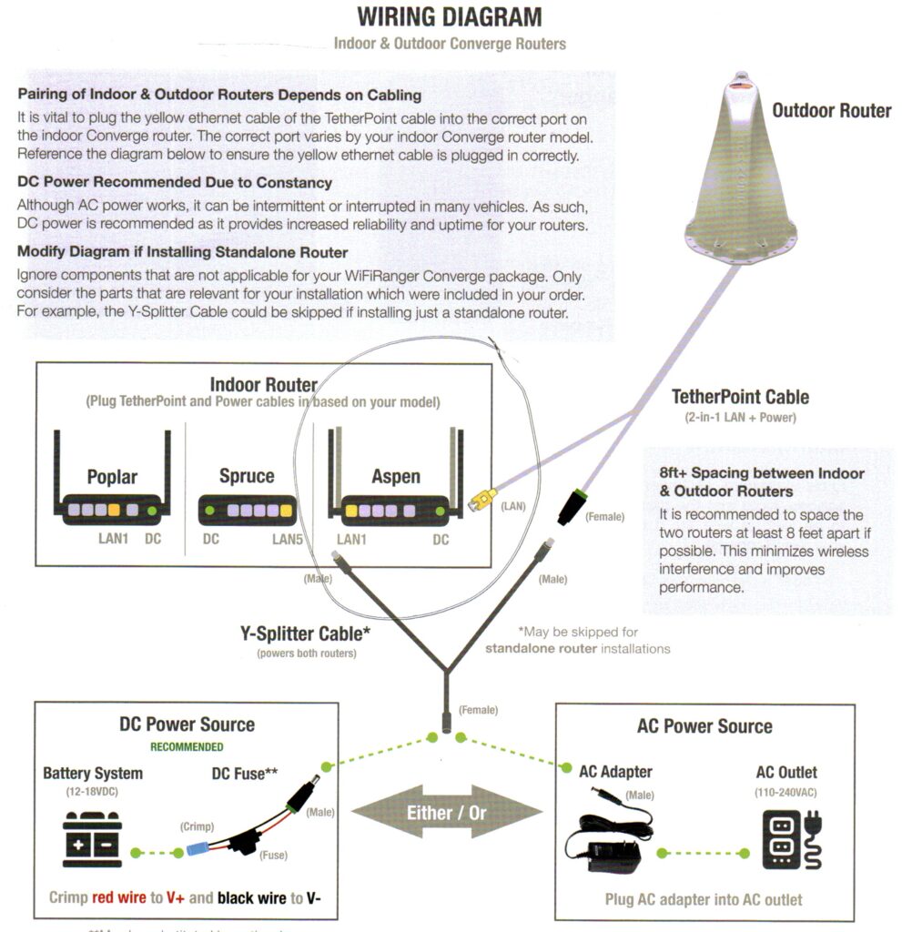
Struggling to debug this on the boat, brought the Aspen home to debug it on a bench. Note that the Denali can’t really be removed without great effort. I had heard that using “port 1” was mandatory for the Aspen to Denali connection. This is also specified in the setup documents that came with the device. Image follows:

WifiRanger Aspen – Dinali setup instructions showing port “LAN 1”

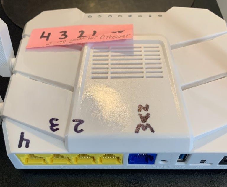
Experimentation on bench using an ethernet connection to house as the wide area connection showed a strange result. The labels on the Aspen for LAN 1 to LAN 4 are backwards! Easiest described in photo of my Aspen router. Looking close at the white case, you can see the 1..4 below the yellow LAN ports. I have fixed it with black Sharpie.

WifiRanger Aspen LAN ports 1..4 are actually LAN ports 4..1

I tested connecting the Aspen to my house internet using ethernet and all of the Yellow and Blue ports. That is, LAN ports 1..4 and the WAN port. Each change required changing the Aspen setup configuration to specify which port was used for the Ethernet WAN connection. To my surprise, the LAN ports 1..4 according to the firmware do not match the LAN ports per the labeling on the Aspen case! I also observed that the Ethernet connection “worked” when in ports 4, 3, 2 and WAN, but did not work when plugged into LAN port #1. Note that this test done with the Aspen told that it doesn’t have a Denali in its configuration, so the Ethernet connection was not competing with the Denali for port 1.

Testing success case

Moved the Aspen back into the boat, turned off the ethernet wide area connection and turned on the Dinali – and connected the Denali to port #1, which is labeled “4”, and I’ve been up for 19 hours straight with zero issues.

Sharing the love here. Let me know if you see similar success and if you post a comment, send me an email (joe at this domain) to let me know so I can approve to the post and get it visible.

Joe Nord

LIMSPEC, HIMEM.sys and EMM386.sys

LIMSPEC, HIMEM.sys and EMM386.sys.  So that this history is not lost, here is more information on expanded memory managers than you ever wanted to know.

What is EMM386?

EMM386 is the DOS 5 implemented device driver to implement an EXPANDED memory manager in DOS using the services of the 80386 processor instead of dedicated hardware.  Your next question: What is an EXPANDED memory manager and how does it differ from an EXTENDED memory manager?  Good questions.  This will take some text to answer, and this was all very important stuff in the late 1980s! 

Nobody will ever need more than 640KB

With the Intel 8088 and the original IBM PC, there was addressability for 1MB of memory.  People describe the original PC has having a memory limit of 640KB, but that is not really accurate.  The machine had 20 bits of memory addressing on the ISA bus and (2**20) -1 is 1MB.  By convention, the bottom 640K is dedicated to software and the high 360KB is dedicated to hardware – such as screen memory.  Much of the hardware space was unused; reserved for possible new hardware, but things were scattered holes, monochrome screen memory being 4KB at B000:0000 for example and the graphics memory adapter living at B8000:0000.  Write bits to those spaces and characters show up on the screen!  Hardware devices are above 640KB and BIOS, DOS and applications are below.  This became not absolute.

When Lotus 123 ruled the world – the 640KB RAM limit was exhausted with large spreadsheets as well as with other large applications. Application implemented paging storage to and from disk was a common work around – but it is slow, and hard to program.  Think diskettes.  Even spinning hard disk media of the day was also dreadfully slow.

More RAM

The first solution was to buy memory cards that plugged in the ISA bus and filled memory space above 640KB inside the holes where hardware memory was not used.  On some systems, it was possible to free the first 64KB of hardware space and add RAM memory to fill that hole and you could end up with a DOS computer with 704KB of usable RAM.  This was interesting, but it was not expanded memory.

What was needed was an ability to get “more RAM” and page that RAM in when needed.

640KB is the DOS limit and there were a few interim 8088 usable expanded memory solutions that never took hold and diverged the industry.  Each implemented “more memory” in an ISA bus card and provided some hardware means to copy memory to and from 8088 visible memory. 

Each application that wanted to use this additional memory, had to code to the hardware of the individual hardware card.  Applications coding to multiple hardware specs!  This is untenable.

LIMSPEC – Lotus Intel Microsoft Specification

Eventually, Lotus, Intel and Microsoft got together and invented “LIM Spec” (Lotus Intel Microsoft SPEC) to standardize this behavior, providing an API that implemented the memory paging to and from memory outside of DOS visible space and this was officially titled “Expanded Memory Specification“, though the programmers continued to call it LIM Spec so they understood which API people were discussing.

Some of the other ones included “XMS from IBM”??  These were not the same.

Hardware

The LIM spec hardware worked via hardware paging.  The LIM spec memory adapter hardware could have LOTS of memory on it – Like 512KB or 1 MB or even more!  I think 16MB was the theoretical limit, but nobody could afford that much memory.

By whacking a few registers on the hardware memory card via I/O bus INs and OUTs, the backing store behind the memory at particular “block” could be changed (was actually called a “page”, but it was a 16KB or 64KB page).  So, if you have a large spreadsheet, instead of paging it to and from disk, you could page it to and from “invisible memory” by touching a couple I/O ports on the ISA bus, which meant you could page this memory in very fast!  Only a few milliseconds!

This was blindly fast compared to other stuff like trying to use the 8088 CPU to copy 4 KB in and 4KB out of some other memory solution.   LIM spec was used primarily for DATA.  One could theoretically move program code to LIM Spec memory, but this wasn’t the normal need. 

The important thing was that it was a standard that an application could code against, and then the hardware makers could produce compatible hardware and know it would work with the important applications of the day.

Standards

Even better, a device driver was written to do the talking to the hardware stuff, once implemented, expanded memory aware applications could code to the device driver LIMSPEC API and the applications were now insulated from how the expanded memory managers implemented paging.

LIM spec was good stuff – but you had a purchase a very expensive card to make it do things.

Intel releases the 80286

Now, there is 16MB of genuine addressable memory (24 bits) – but DOS still knows how to use only 1MB.  RAM is also becoming cheaper but still nobody could afford 16MB, it was common at the time for machines to come with 2MB of RAM.  If only DOS could see higher than 640KB, this memory could do something useful and there is lots of it.  2MB is a huge increase!

What is EXTENDED memory?  

EXTENDED memory is the genuine 80286 visible system memory that is present in the machine, but isn’t usable because DOS can’t see that high.  It is the stuff above 1MB.  It is just memory, but it is called “Extended” so that you know it isn’t DOS normal memory. 

Note that “extended memory” as a concept is incorrect, its just memory and all the memory present in the machine is addressable by the processor, the fact that DOS and applications under DOS understand only the memory below 1MB is just a statement to the architecture at the time.

Hardware ISA bus implemented LIM spec solutions still selling well at this time and the standard API exists, it now became possible to use the 80286 addressable extended memory to implement LIM Spec!  In concept, use a couple GDT selectors of the 80286 and you can page memory to and from EXTENDED memory to accomplish LIM Spec, and usable by DOS and most importantly, cheap!  No longer need a hardware memory card.  But, the 80286 was never an important chip, so these techniques never took off, the hardware solutions for LIMSPEC kept selling.

VCPI – Virtual Control Program Interface

Virtual Control Program Interface (VCPI) became a standard for running applications in the protected memory space of the 80286.  Here you could load PROGRAMS into the 80286 high memory and run that application code!  Quarterdeck with QEMM were the players here, but I’m going from a long ago memory.

You had to “come back to DOS” for OS functions or I/O with device drivers, but you could put gobs of program and data up high.  I once wrote application programs under VCPI; it was a small part of the DOS programming world that most people did not understand. Getting I/O to work to external hardware required writing code to “switch” to and from protected mode.  The 80286 was a stepping-stone to the right solution.  Yes, it would be possible to write device drivers in the high memory space, but interrupt delivery was space of the VCPI and this was not a common thing.

DPMI (80386) – DOS Protect Mode Interface

The market progresses and the Intel 80386 CPU comes out, a CPU with all the things one expects in the modern world.  It has selectors rather than segments, just like the 80286, but it also adds page-table based memory addressing and MVDM (multiple virtual DOS machine) support.  To be fair, the 80286 also had selector-based addressing, but it was the 80386 processor addition of page tables that really made it possible for solutions to high memory addressing. 

The execution of applications in high memory under DOS on the 80386 was governed by DOS Protect Mode Interface. 

80386 and DPMI

PharLap was another player on the high memory execution front, and the definition of DOS Protected Mode Interface.  This provided a standard means to run programs in the high memory space, but it also implemented LIMSPEC in software which performed every bit as efficiently as LIMSPEC in hardware memory expansion cards.  More efficiently actually because the modern 80386 machines and their RAM were hugely fast compared to ISA bus implemented RAM and the page tables of the processor could be quickly programmed to change backing store for LIM Spec paging.

Running application up high required a memory manager to accomplish, but the same techniques needed to manage the high memory, could also be used to implement LIMSPEC.  During boot, you could load “DOS” device drivers which was really the extended memory manager, which put the machine into protected mode, and implemented DPMI and LIMSPEC.

DPMI provided a standardized method to get programs and data into high memory spaces.

The biggest runtime for executing applications in this high space was DOS4GW.exe distributed by Watcom.  PharLap was the main player in the memory manager space, with the PharLap DOS extender.  Exactly the relationship between PharLap and Watcom, I do not know.

DPMI was quite successful.

Microsoft releases DOS 5

DOS 5 included HIMEM.sys and EMM386!  The functions of LIMSPEC and DPMI were brought to the market with DOS, and no need to purchase an expanded memory manager, and within 6 months, PharLap folded. 

  • HIMEM.sys puts the CPU into “protect mode” — Implements DPMI
  • EMM386.sys uses the services of HIMEM.sys to implement “Expanded Memory Management (LIM Spec) using the 80386 CPU

I am partially vague on what is implemented in HIMEM.sys and what is implemented in EMM386.sys. The functions varied over time or at least my understanding of them and there were other drivers involved.

Who provides the DPMI manager?

One of the PRIMARY THINGS of DPMI is that all DPMI applications can INCLUDE a DPMI memory manager in their binary.  The rule is that if a DPMI manager has not yet been loaded – you BECOME the DPMI manager.  If one is already there, you use its services and do not load your memory manager.  This also became not absolute over time. 

If the DPMI manager already running is “old” – you can perform a coup.

You can also package the executable separate from the memory manager.

Thankfully for the market, once DOS 5 included the DPMI manager, the need for application programs to carry one along went away and the world became a more stable place.

Windows 3.1 to Windows 95

The most successful DPMI application ever was Windows.  Starting with Windows 3.0 Enhanced mode along with Windows 3.1 and eventually Windows for Workgroups 3.11.  Over time, more and more OS code was moved from DOS space to high memory space, and eventually Windows 95 was born.  Windows 95 while celebrated as a great new operating system, was really a very large, DPMI application running on top of DOS.  Andrew Schulman documented this well in his book Undocumented Windows. 

Eventually, Windows NT took hold as a “real OS” and once the world got to Windows XP, the days of DOS were behind us.  Except, its 2022, and yes, DOS is still running.

DOS 5, 6, 7

As DOS matured, the management of the hardware memory gaps above 640KB became well managed.  By this time, much hardware allowed its hardware memory address to be configured in software, making it easier to produce large “gaps” in the memory above 640KB and below 1MB.  Careful placement of device drivers during boot into these holes allowed maximizing of DOS memory below 640KB and the memory managers of DOS made this organization possible. MEM.exe included with DOS made it possible to get a clear map of all the memory being used and a bit of careful adjustment could produce a very cleanly running machine with RAM available for DOS and applications maximized.

Conclusion

There are places in this blog where the information is “good”, but also likely incomplete.  If you have more details, please add in the comments – and send me an email at joe at this domain.  The blog system is set to not post comments unless approved, and I’ll need a little kick to move them to published.

Joe Nord
Dinghy tow harness in action

Back in August, I wrote a pretty detailed article on construction of a dinghy tow harness for use with my Highfield 330 Dinghy being towed behind catamaran sailboat. That article is here. Today, with completion of a 500 mile tow, I can share images and videos of the tow underway as well as lessons learned on the construction and use of the dinghy tow harness.

First – everything worked fine. We drove the boat Fort Lauderdale to St. Augustine, round trip, most of it in the ICW, with two big sections in ocean. On the southern journey, the Southern Boulevard ICW bridge was closed for several days and after waiting for a while, it became necessary to tolerate some bad weather going out West Palm Beach and back in at Hillsboro Inlet. This provided a pretty rugged test for the dinghy tow harness. Going out West Palm Beach, the waves were big and nasty and no time for filming. Classic inlet stuff with big crests and large waves. We made 2.2 knots as the ocean beat up the big boat, and sloshed around the dinghy in big seas. When things calmed down a bit, I was able to film the dinghy tow harness in action in “rough” seas. I must say that on video, the ocean looks much calmer than it was in person.

Back to the design

Recall the dinghy tow harness connects in 3 points and the center point is designed to only take a load if one of the port/starboard connections fails. See the prior blog for excruciating detail, but the math on how long to make the center connector, worked out to be solid.

Things came loose

Did I expect things to come loose? Definitely not.
Did things come loose? Demonstrably yes.

Trip was 3 weeks and the first time on the trip that I found a disconnected carabiner was after waking up in an anchorage in the middle of nowhere north of Cape Canaveral. When did it come loose? Probably in the 15 miles stretch of rough water north of Haulover Canal. I recall hitting several good size yacht wakes and next day, one of the carabiners was loose! A couple hundred miles in before a disconnect, but yet there was a disconnect!

In the spirit of good engineering, a problem that cannot be reproduced, is not a problem, so reconnect, push on, keep an eye on it and see what happens. These carabiners are massive, with strong springs and they are hard to get attached to the dinghy. They should be even harder to have them come off of the dinghy due to wave action!

We made it to St. Augustine, had a great time in the city and prepared for the return trip. A day or two in, hit the same 15 mile stretch before the Haulover Canal. Again rough, NASTY weather, squalls, pouring down rain. Get to the turn for the Haulover Canal and … a carabiner is loose! This time, the other side, so the problem is reproducible and it isn’t the fault of the specific carabiner! No time to fix it there, towed the dinghy using only two connect points through the canal and onto smoother water on the inside.

How can these things come loose?

Hypothesis, later confirmed: The propensity of the carabiner to come loose is related to the orientation of the carabiner on the dinghy! I switched the carabiners to the “right” method and for the rest of the way home of 200+ miles, including ICW and ocean in rough seas, no failures.

Spring side of carabiner needs to be pointing “down” or toward the “inside” of the dinghy

Here is a collection of images and videos of the trip.

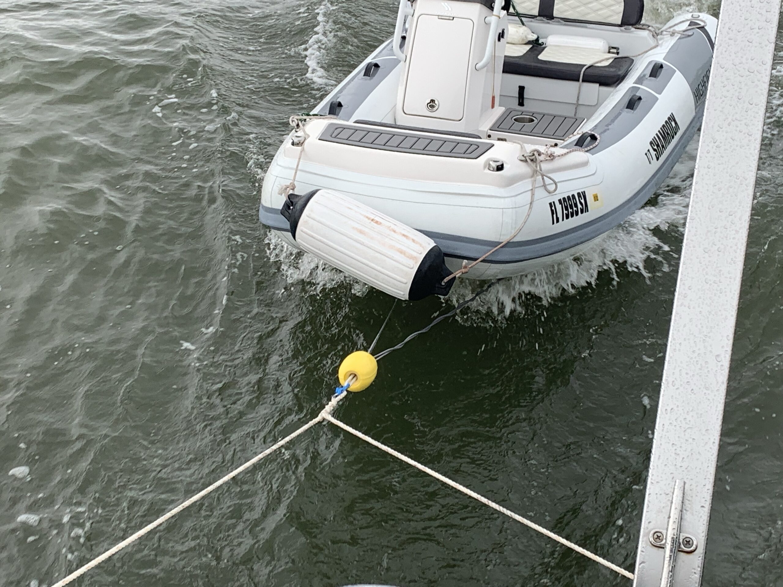
First one shows the dinghy tow harness after the starboard carabiner came loose and the starboard rope then wrapped around the port rope. It towed fine here as planned with the middle connector picking up the load.

Next picture shows the “good” carabiner orientation. If this way, it stays put. If reverse the orientation, experience says that the carabiner can find its way loose after many miles and getting bounced around in choppy waves.

Orientation of the middle connection didn’t matter. The port/starboard would come loose if the spring was “up” or “to the outside”. If the spring is down, it stays put. WHY? I don’t know, but I can say what when it came loose on the ICW, it was at a point of yacht wake and big bouncing. Something happened to allow it to slip loose and I was amazed to see it happen in real time. No fear here, would have to loose two at the same time for it to be a problem, but was still interesting to see. Bottom line, with the spring to the inside, hundreds of miles in test, and no failures. Getting that orientation right when clipping on the carabiners from above, in the water, takes some effort.

For videos, here are links to youtube.

Towing dinghy on ICW after 1 of 3 carabiner came loose

Towing dinghy in ocean in pretty rough water.

Towing dinghy in Ocean in pretty rough water

And for the final video, again towing the dinghy in ocean, in calmer water.

From here, made it the last 8 hours to Hillsboro Inlet and home. Once switched the dinghy tow harness to have the springs toward the inside, no more disconnects.

Why don’t you lift the dinghy onto that set of davits on back of boat?

The big boat has a dinghy lifter, that doesn’t work. Its in the process of bring repaired and all the electronics have been replaced. The hydraulic cylinders are still a TBD and that means I can’t lift the dinghy. Completing this project really can’t come soon enough. Towing a dinghy 500 miles can be done, but it is WORK. The dinghy is something to complicate every bridge, every docking, every anchoring. What more it also means that the dinghy gets marine growth and cleanup after a 3 week trip, is real effort.

Final thoughts – Speed and fuel

There are many good jokes that roughly say that people with yachts don’t need to worry about the price of fuel. I still measured it and found it interesting to see observe that towing the dinghy causes the big boat to slow 0.7 knots (a 15% loss in speed) vs. lifting the dinghy. Towing the dinghy also causes a 26% hit to fuel efficiency. This was more than I expected. This isn’t a fast boat, so the dinghy has a larger effect than it would on something more substantial.

Fun times, let me know if you find things interesting.

Joe Nord

Dinghy tow harness

I have a Highfield 330 Sport dinghy and I’ve been through a few dinghy tow harnesses. I now believe I have a solution that will stand the test of time, allowing all 3 attach points to be used for redundancy, and still allowing close control of where the dinghy tows behind the larger boat. This post details the design and provides photos of the end product, I hope it can be useful to others trying to solve the same problem.

Yes, that’s a new dinghy! Yes, I bought a tow harness when bought the dinghy. NO, the carabiners on that original tow harness did not fit onto the boat connections and even the replacements I first used were not up to the job, and stretched. Solving this problem right requires going full on Tim Allen on the carabiner size, moving up to some really good strong rope for the dinghy bridle, and selecting rope for the connection to tow boat that will stretch.

Wanting to do this right, instead of a 2 point connection for the dinghy, I have gone with 3, with the center connection always slack, only to take on load should one of the port/starboard connections fail. This will pull the dinghy toward the middle as it bounces around in the normal configuration, yet not pull the dinghy sideways, and likely sink it, or rip the cleats out of the back of the towing vessel if one of the side connections fails. I’ve never seen that happen, but the idea of it is pretty terrifying, so I’ll add that 3rd connection.

While I’m pretty good at splicing 3 part rope, moving up to dyneema requires some special skills, so I have enlisted the paid support of the rigging specialists at West Marine main store in Fort Lauderdale. I provided specs on the length of lines, they built to spec and I must say, the outcome is pretty much spot on. The splice on the tow boat line is also impressive – I’m not sure how one splices a thimble into the middle of a rope, but here it is, done.

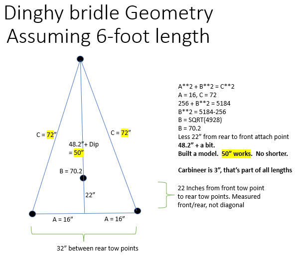
First problem, how long should the 3 bridle segments be from the dinghy to the attach point? The length from my prior dinghy harness was 6 feet and this worked pretty well, so stuck with it for the port/starboard connections. This time though, I’m adding a center connection and this is from a spot closer to the tow point, so it has to be shorter. How much shorter? Long enough that it will never take a load unless something else breaks, but as short as possible so that if it ever does take a load, it will tow the dinghy as near to straight as can be accomplished. Very little slack!

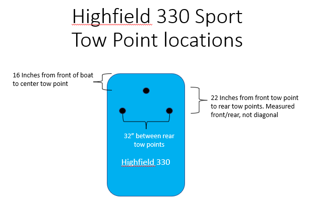
Here is a diagram of the dinghy’s three tow points. The two main points are at same position from forward/aft point of view and the center point is closer to the front. The forward point and the aft points are “same height” or close to it, so there is little to worry about from an up/down perspective changing the required length of the center connection.

Tow point locations – Highfield dinghy

A side note on Metric vs. American. I know this will come up, so best to get ahead of it. The dinghy is a Highfield 330. That is METRIC, even though it seems to be off by a factor of 100. My tape measure however only knows inches, and feet, so that’s what I used for the measurements. I would prefer to use a cm tape measure, but unfortunately, I don’t have one of those. I’ll work on this. Back to the math…

Broke out geometry and Pythagorean theorem to calculate the required length of the center connection.  

a2 + b2 = c2, or as programmers prefer to write a**2 + b**2 = c**2.

With the side connections at 72″ and the middle connection 22″ ahead, the “same” length for the middle connection computes out to 70.2″, less the 22″ head start, equals 48.2″. We want a little slack – very little slack – so I had the middle line built at 50″ vs. the sides at 72. This provides 1.8″ of slack on the middle line, which worked out about perfectly. Details in the diagram that follows.

Dinghy tow bridle center line length calculation

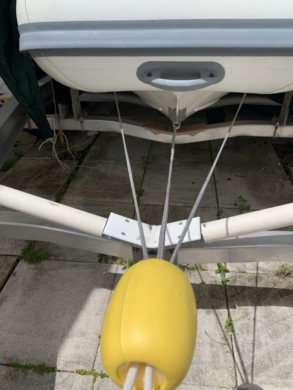
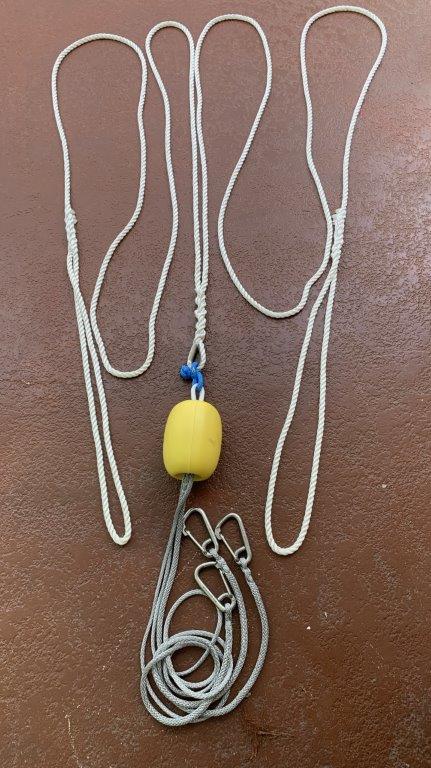
Adding a float on the front completes the assembly and it looks like this connected to the dinghy. Notice that the center connection is “loose”, the carabiner on its connection at the dinghy has a bit of slack. The end connections take all of the load and given this is dyneema, nothing should appreciably stretch.

Dinghy bridle connected to dinghy

I add that this is 1/4″ dyneema and that’s pretty light, but according to wise people, this has a break strength well beyond the tow rope that will go from the dinghy bridle to the tow vessel. The connection points on this aluminum bottom Highfield are also pretty impressive, large and welded right into the foundation of the boat.

I have had trouble in the past though with carabiners stretching, so went with West Marine “4 inch” carabiner part number 274340. They aren’t giving these away! At $32.29 each, times 3, this adds up to nearly a 1/3rd of the full bill of materials.

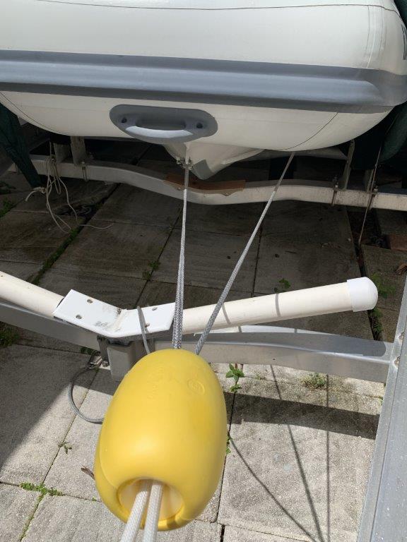
The next photo shows what happens when one side fails…

3 point dinghy bridle showing move to center when a side fails

Notice with the starboard line disconnected, the load immediately transfers to the center, and port. Still being pulled by two cables, and still mostly “forward”. This is the goal of the 3rd connection. Keep it long enough so it isn’t involved in normal towing, but when one side fails, it immediately picks up the work and keeps the dinghy towing mostly “forward”.

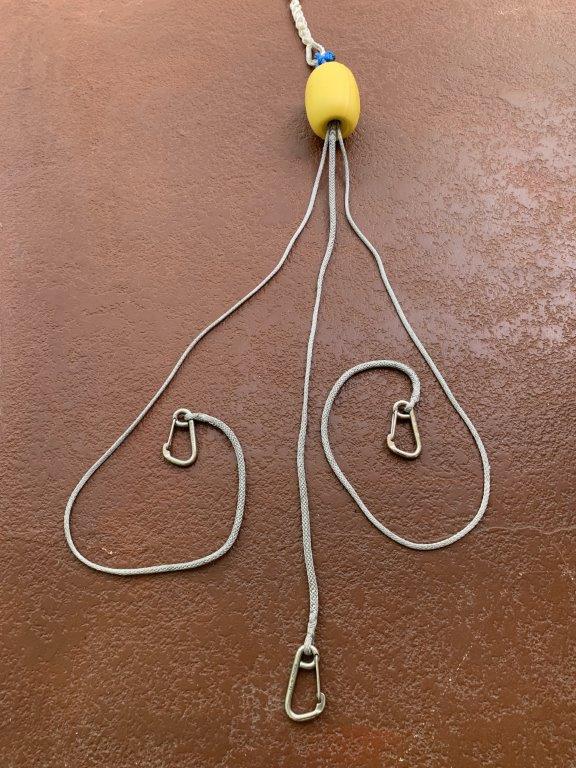
Dinghy bridle close up

Here is the dinghy bridle in one photo. The dyneema splices on the big carabiners are … clean. All go back to the tow point, where a float is added to keep the whole thing in front of the dinghy when not actively towing and keeping it from going deep when trying to get things disconnected. The full dinghy bridle is also “short enough” that even if we drive over it when disconnected from the tow boat’s tow line, the lines will not make it all the way back to the dinghy’s prop.

The next step is connection from the dinghy bridle to the tow boat bridle.

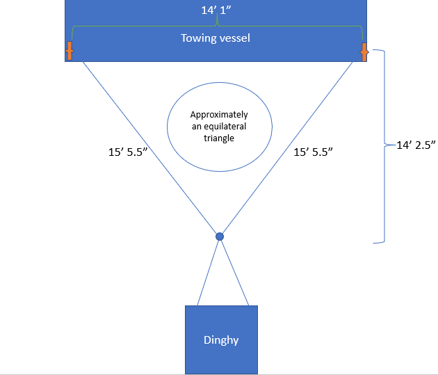
Tow boat bridle – equilateral triangle

For the tow boat connection I like an equilateral triangle, which makes the normal pull be from both cleats, and when going through bridges, easy to pull the dinghy up tight on one side, without having to mess with the other side. This keeps the lines out of the props and keeps the dinghy close where it can’t get into mischief while waiting for bridges. Yes, it bangs into the tow boat during this maneuver, but it is inflatable, so no worries. You can even “back over it”, and the lines stay out of the props! Doing it again, I’d probably make this triangle “taller”, moving the dinghy away from the tow boat by another 5 or so feet. Still safe from ropes in propellers, but making the tow pull on the cleats more direct to the rear.

The 60 degree angle coming off the back of the boat in my case though makes the tow bridle not hit any railings, so it works. For these lines, I used 7/16″ nylon, which will stretch. And yes, when towing offshore, it will be wise to add 50 to 100 feet of additional line on the connection between the tow boat bridle and the dinghy bridle, or just raise it up on the dinghy lifter, which I’ll save for a later post.

Dinghy bridle full rig

The full rig is in this photo. Notice that the eyes for cleat connection to boat are large; they are about 16″ going over 12″ cleats which is really unnecessary, but it makes it easy to connect and disconnect. The blue connect point is a dyneema soft shackle. I am suspicious of soft shackles, I’m not yet sure if this is a winner. It was much kinder to the wallet than the alternate solution of Tylaska Snap Shackle at $192.95. Time will tell how this decision plays out.

My concluding thought is a question. Why does it seem that everyone builds their own dinghy bridle? To take a stab at the answer, I expect the variety of connection points on dinghies make the “right” configuration a per-boat item. Bridles from mass product companies have to hit the majority consumer so really are not “right” for anyone. Boat widths vary, adding a 3rd connection point really messes up the mass market configuration. In the case of the bridle I purchased when got this boat, it was also too wimpy for the job.

In today’s case of this custom build, by taking careful measurements of the dinghy and adding some math for calculations of desired length of the middle connection, plus good help from the West Marine rigging shop (Thank you Charlie) the outcome is a dinghy tow harness that I expect will serve me well for a number of years.

Joe Nord

Activated Disqus

Thank you all who have commented on this blog and gone through the manual steps to sign up with an account on the WordPress system, author a comment and then wait for me to see it, and approve before it becomes visible. This whole thing can take a day or two on a good case and that lag time really plays against interactive nature of discussion.

In an effort to make comment posting “immediate” it is necessary to remove humans from the loop. I have set up an account on Disqus and added this site to the discussion forums.

Near as I can tell, when set up Disqus, this deactivates methods of posting on WordPress blogs which are not Disqus. That feels a bit overreaching, but its likely the right call as the real goal on this is to involve reputation in the automatic approval and posting of comments. If you are a known person who hasn’t spammed the world in other forums, then you get immediate posting here.

If you have experience in the Disqus blog commenting space I appreciate hearing what you have learned, please comment below. I fear what can happen when the world of possible robots can comment without filters. Time will show how this experiment plays out.

Update: August 20, 2021

Received notification from Disqus that my site has been approved for ads! Or, I could sign up at the paid level for $11 / month. That’s more than I want to pay and the idea of putting ads on my site to pay for the tool, well no. So I’ve bowed out and removed the plugin. It was a good experiment, I’m back to WordPress comments and a return to delayed vision of reader posts as I have to review them before they are shown.

Triangle Peg Game – All Solutions

Many years ago I wrote a web posting of how to solve the Cracker Barrel golf tee triangle board peg game puzzle. This is now located on this blog in a preceding post here.

In updating that blog for a solution of finish hole equals to the starting empty hole, I was troubled that the solution provided by reader Merv Eberhardt included a solution for 4 of the possible 5 starting holes, but did not include a solution for the evil hole #5

Related, I had never been able to get to the goal position or “magic diamond” from a starting position of 5, 8 or 9. Recall that once 3 moves are complete for all the other starting positions, the solution to the puzzle is the same in all cases. I mean, a solution to the puzzle is the same in all cases, there are lots of variations on the solution to the puzzle. The nice thing about the solution discussed in the prior blog is that after 3 moves, all the solutions are the same no matter where you started, except position 5 which is same as 5, 8, 9. Goal position or “magic diamond” is listed below.

I asked that if anyone could figure out how to get to the goal position from start position 5, please let me know. Today: I know there is no such solution.

Wrote a program

Troubled that I did not have a finish position equal starting position for hole #5, I wrote a program to solve the puzzle. Solve it yes, but I mean solve ALL of the variations.

From any position, you can jump up-left, up-right, left, right, down-left, down-right. The program starts with one position empty and then solves ALL of the possible solutions for that position, and then moves onto the next starting position, until all of the solutions are known. As a programmer, this was itself a good puzzle, much like playing the game.

The answers are

  1. There is no path to the magic diamond from starting position 5 (5, 8, 9)
  2. There is no finish in same hole as started for position 5 (5, 8, 9)

Some other neat stuff came out of the exercise though! Among the more interesting observations is that while there are 1,550 solutions to starting hole 5, every single one of them finishes with the last peg standing in position 13! This means that in reality there are very few solutions to starting position 5.

Statistics

Just as the starting holes of 1, 11 and 15 are really the same puzzle rotated, there are numerous methods of solving the puzzle which are just variations of the same solution. If you switch a couple jumps in sequence, or jump in opposite directions, you can produce many more solutions which are really the same solution.

How many solutions are there for each starting hole? Glad you asked!

Start-PegWinnersLosers
12976017739865
2148809213994
3148809213994
48525835180925
515504528807
68525835180925
7148809213994
815504528807
915504528807
10148809213994
112976017739865
12148809213994
138525835180925
14148809213994
152976017739865
Total438,984227,632,755228,071,739
Peg game winning solutions and losing positions

Solutions posted online

In case anyone else wants to tear this apart, I have posted in CSV form, ALL of the 438,984 solutions to the game. You can download here. This file is 45MB in size.

Joe Nord

Triangle Peg Board Game – Solutions to amaze your friends

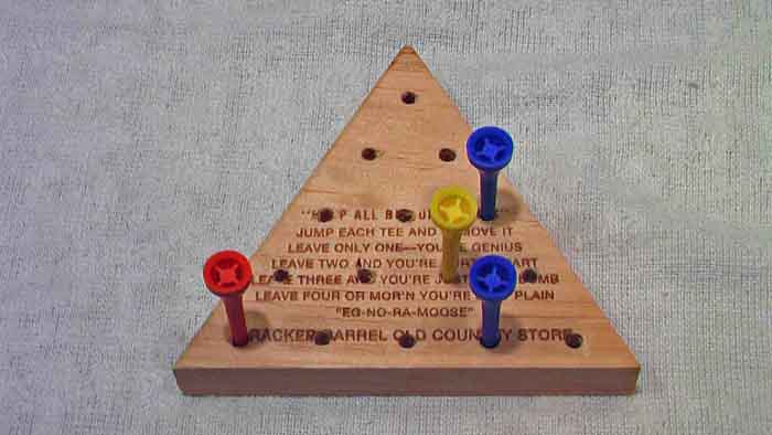
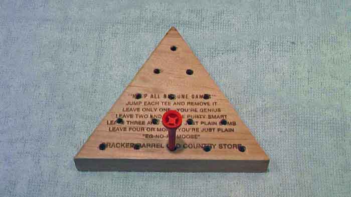
When visiting the Cracker Barrel restaurant, you will find a 15-peg triangle board game on each table.  This page describes how to solve the puzzle from any starting position.

Update: June 2021. Moved from web page to blog and added solutions for finish position equal start position.

The game board is a triangle with 15 holes in the same shape as bowing pins, except with an extra row.  The game starts with pegs (golf tees) in all the holes except one; the goal is to jump pegs one at a time, removing the jumped peg until only one peg remains.  The instructions on the board say that if you leave only one peg, you are a genius.  I suspect that the genius title is overstated, but if you follow the instructions on this page and you’re sure to impress the family!

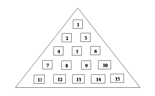
For the pages that follow, the puzzle is viewed in this orientation and the hole numbers referenced.   

Triangle peg game hole numbers

Photographs follow showing the board from start of game through completion.

The normal starting hole (empty hole) is hole #1.  The initial discussion on this page shows how to solve the puzzle with hole #1 empty.  That is followed by instructions on how to solve for the other starting positions, with the happy addition that most of the starting positions are just variations of the standard #1 start.  After 3 moves, they all look the same; except the evil #5!

The first 3 jumps are:  4-1, 6-4 and 1-6.  With these complete, the “magic” base follows.  This shape will be referenced later in this document as the “goal position” for the other variations of the game using different starting holes.  Learning to solve the puzzle from this point is the key to success with the game.

The next moves, 7-2, 13-4 and 2-7. This shape is not too critical, the photo just shows the puzzle progressing.

The next steps are to clear the second from bottom row (the yellow tees) and the bottom row.

First, 10-8, 7-9 clears the second row.

15-13 and 12-14 clears the bottom.  To mix it up, jump them in reverse and it won’t look like you’re solving the puzzle the same way every time.

Almost there, the diagonal jump clears all but the bottom of the puzzle and the bottom clears “easy”.

6-13, 14-12 and 11-13 ==> Winner!

Starting position (1) – Full solution

41
64
16
72
134
27
108
79
1513
1214
613
1412
1113

For the other starting positions (except position 5 which we will cover later), the same solution is used after the third jump.  The “trick” is to get to the same pattern after the first three moves, the goal shape.  From there, solve solve as if it were starting position 1.   Notice that there is only one sequence to remember as you can get to the goal position from any of the starting positions based purely on shape.

Here are the moves for “after” the goal position is reached.

72
134
27
108
79
1513
1214
613
1412
1113

How many starting positions are there?

There are 15 pegs in the board, but only 4 starting positions.  For example, all the points are position “1”, even if they are otherwise called “11” or “15” the puzzle is the same once you rotate the board; even if only mentally.   2 and 3 are really the same if you view them “mirrored”.  Even if seen backwards, after the first 3 moves, both line up for the same standard solution.  Starting positions 4/6 are also swappable; 13 is the same as 4/6 once you rotate the board.

Here are all the starting positions.

11, 11, 15
22, 3, 7, 12, 10, 14
44, 6, 13
55, 8, 9

The neat thing to observe is that start positions 1, 2 and 4 and 11, 15, 3, 7, 12, 10, 14, 6 and 13 are really the same as they have the same solution once you get past the first 3 moves!   This means that there are only 2 puzzle solutions that need to be memorized to solve all positions on the puzzle.  If someone figures out how to get to the “magic” 3rd position when start with hole 5 empty, please let me know.

  • Update June 10, 2021 – there is no set of moves to get to magic position from “5”

First three moves for starting position (1, 11, 15 — Collectively called “1”).

Starting holeMove 1Move 2Move 3Comments
1, 11, 154-16-41-6 
2, 3, 7, 12, 10, 147-213-411-13Rotate right
4, 6, 1313-410-815-13Rotate left

The middle holes

I have not found a method to get to the “same as the others” solution when start with hole #5 (aka 8, 9).  A full solution follows and interestingly, it also ends with the final peg standing in hole 13; there must be a good reason.  With practice, solving this “hard one” is really just remembering that there are only 2 possible first moves and this solution starts from the right, the next couple moves are filling the pegs just jumped over or from and the 4th is opening the middle hole on the right side of the triangle.  From there, it pretty much solves itself! ?

145
79
27
64
72
14
156
310
1214
108
413
1412
1113

Finish hole same as start hole

Feedback from reader Merv Eberhardt provides an interesting twist on the above solution. He wanted a solution where the last peg ends up in the same position which was empty at the start. Taking genius to a new level…

The solutions below achieve this goal, and I note that they all also achieve the magic diamond after 3 moves, so it is really the finish that is varied to move the ending position from hole 13 as is listed above to instead finish at the position which was empty at start.

1 (11,15) 2 (10,12) 3 (7, 14) 4 (6,13)
4172103134
641341361513
1611131513108
10314121214310
1366134131214
31012141412413
156151311131315
7227310156
1113161414
14121037272
125382964
6413413627
4172103114
Peg Game solutions finishing in same hole as start

WordPress SMTP email notifications on GoDaddy

In setting up WordPress recently on this website, I discovered that getting SMTP working for blog email notifications was more complicated than I expected. This post shows the solution.

No, I don’t have the ability for anyone to post or comment yet, but someday that will come and it will be sure welcome to get notifications. In past, before moving to WordPress, I posted some nice content on things like how to tie boats up in canal for hurricane preparation, link. People commented and I saw the comments a month or more later. I send apologies to the folks that wrote comments that seemed to go into a black hole. Having notifications now working will allow me to be more timely in response and even will allow me to respond inquiries on “contact me”, assuming robots don’t send too much spam. Yes, they will. I know.

Convincing WordPress to send email notifications though was a tricky process. For starters, GoDaddy with CPANEL has TWO email systems:

  1. The right one, which is email system which is secureserver.net and
  2. CPANEL based site hosting of own mail server – yoursite.com/cpanel email accounts

The 1st one is the one needed to get email notifications to a place you can see them, so its the one to work with. The 2nd one is a distraction and will only send emails within your own domain. An interesting note is that in my prior usage of B2evolution, the automated setup of email in that tool configured the UNIX email system in “2”. This didn’t work but once I figured it out, wow were there a lot of emails in those invisible accounts.

Build an email account for sending messages

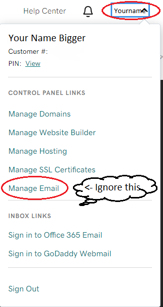
The first step is establishing an email address dedicated to this purpose and on GoDaddy, the way to define new email addresses is on the GoDaddy account management area, not in CPANEL of an individual domain. Logon at godaddy.com and then ignore the following panel in the top right which is a distraction. Hitting the main menu on the main website is NOT the way to define new email accounts. Here is the panel that you shouldn’t use.

The right place to define email address

The right place to define a new email address is https://account.godaddy.com/products. Scroll down, way down, and find Workspace Email. Click “Manage All”.

Now in the right place, define a new email address such as wpadmin@yourname.com or similar. Emails sent from blog system will come from this address. You should also set this up in your email program to verify it works. I note that it is POP3, not IMAP in my case and this has to be correctly configured or the email send/receive will not work. Once get the email account functioning, it is time to configure WordPress to send notifications via SMTP.

Configuring WordPress to send email

You would think this is as simple as installing a plugin in WordPress that knows how to use SMTP to send email, but there is more to it. A plugin is required and I selected Easy WP SMTP. The WordPress “Add Plugins” page looks like this.

After installing the plugin, it must be activated

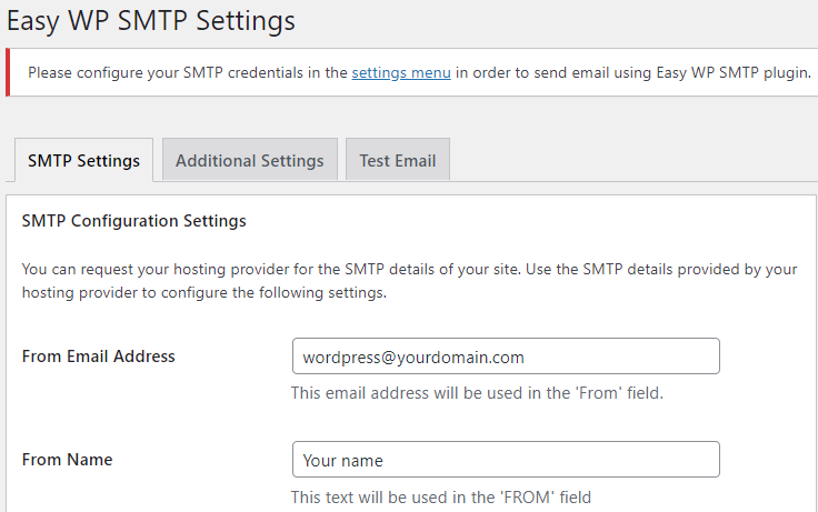
The next step is to configure the plugin to use the email address earlier created. The first page of the settings is straight forward.

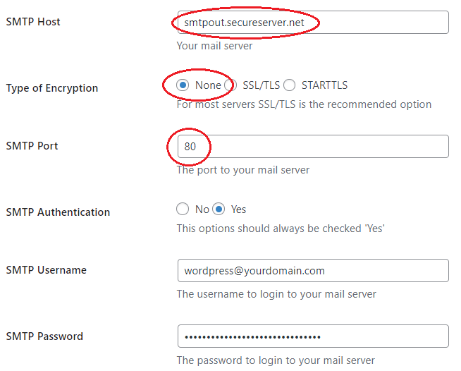
The second page of the settings is where the issues arise and where I hope this blog can help other folks who have got caught by the same confusion as me.

For me, the critical piece of missing information was explained in this youtube video by David Repasky. In that post he covered additional items, but the key material for me was learning that the port for SMTP send via smtpout.secureserver.net should be port 80 and not 465! Thank you David.

On the GoDaddy hosting, the UNIX machine hosting your website is close to local network and can talk to smptout.secureserver.net over ports that are not correct on the external Internet network. Notice that this means that information is traveling not encrypted on GoDaddy’s internal network segments. Is that a problem? I don’t know, but I must expect that GoDaddy have evaluated this configuration.

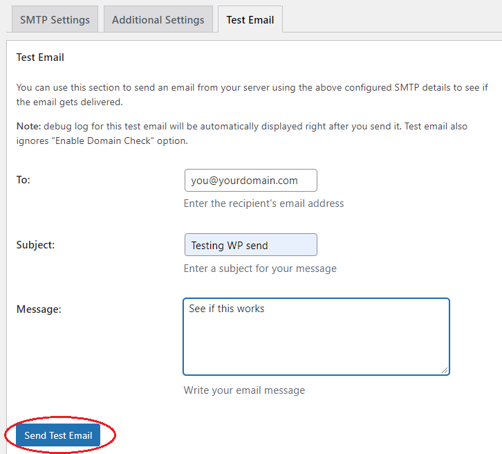
The final step is to send yourself a test message, as here.

With Easy WP SMTP configured as above, the email comes straight through and arrives almost instantly.

This took some time for me to dig through. I hope this write up helps others.

Joe Nord

Moving into WordPress

Updated my website to use version 8.0 of PHP and B2evolution stopped working. Was able to repair it enough to see blog posts again and managed to extract the content. This was the sign I needed to retire the old blog manager and move into the times with WordPress.

Technically I used WordPress before B2evolution, but it had some security issues that inspired me to move away. See blog post on this site about LAVE is Eval spelled backwards, link, and checking the date, wow, looks like that was 2014. From there, I moved to Blogger and some time after moved everything, except one post back to personal website. That post had wide reading and lots of links to it, so left it be.

Why did I select B2evolution? It was not WordPress and wasn’t something bad actors were attacking. I had become very tired of spam comments continuously showing up on on blog in prior usage of WordPress. Yes, this is security through obscurity, but hey, it worked.

Years gone by, it is 2021 and I move back to WordPress. I must say that with 7 years of active maintenance and enhancements, WordPress is very impressive compared to the B2evolution blogging system. I’ll write some posts on the experience.

Joe Nord